
Q1 2N3904 (EBC), 2SC945 (ECB) or equiv (please double check pinouts!!!)
Q2 2N3906 (EBC), 2SA733 (ECB) or equiv (please double check pinouts!!!)
R1,R2 1K ohm (brown-black-red), 1/4W
R3 150 ohm (brown-green-brown), 1W, or 3x series 47ohm 1/4W.
 Hardware hackers know all this too commonly now. They upgrade their old
motherboard to a new one with a 4-pin on-board PWM controller. They try to
save their really cool heatsink/fan, but the
fan is the traditional 3-pin tachometer fan. Sure, it plugs straight in
to the 4-pin fan slot but it runs at full speed all of the time.
Hardware hackers know all this too commonly now. They upgrade their old
motherboard to a new one with a 4-pin on-board PWM controller. They try to
save their really cool heatsink/fan, but the
fan is the traditional 3-pin tachometer fan. Sure, it plugs straight in
to the 4-pin fan slot but it runs at full speed all of the time.
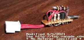
It works fine, it cools fine, but sheesh it generates so much noise. This hack adaptor, using two transistors and a few resistors, provides some PWM control over these 3 wire fans at the expense of some tachometer accuracy.
Just like all other hacks found on the Internet, no warranty or guarantees are expressed, you are responsible for all damage incurred by using this modification. Possible side effects especially if you wire this wrong include destruction of your motherboard, CPU, fan, or any combination of them or more.
PWM Amplifier Circuit:
Reproduction warning: this circuit may not be used in any commercial product
without first contacting the designer. Post message on
Midgar's mess if you want to commercially build this.
Q1 2N3904 (EBC), 2SC945 (ECB) or equiv (please double check pinouts!!!) Q2 2N3906 (EBC), 2SA733 (ECB) or equiv (please double check pinouts!!!) R1,R2 1K ohm (brown-black-red), 1/4W R3 150 ohm (brown-green-brown), 1W, or 3x series 47ohm 1/4W.
Improvement suggestions: Lots of room for improvement. The minimum speed circuit should also use PWM. Currently it uses R3 which wastes power, but simplifies the circuit a lot (not to mention it allows the tach to work.)
Circuit construction notes: none. Don't go too wild on R3. Double check your pin wiring before connecting.
Fan notes: 12V DC fan only. Do not hook up a fan rated for more than 180mA nominal. Tested with 120mA fans. Risk of frying Q2 and R3 by exceeding these limits.
I'm using this with my Zalman CNPS7000AlCu with the Socket 775 bracket on my Core2Duo E6700. The machine runs fairly cool as-is and I've never seen it change speeds too often, except during reboots. As this machine was destined to be a PVR machine, it needs to be fairly quiet. In fact I had to force it to specific speeds to see that the circuit works because the Core2Duo is such a cool chip. :-) I get around 2700RPM to 3800 RPM speed control (30% PWM to 100%), which isn't much, but at least I didn't have to get a new fan. And I can definitely hear the difference. I'll have to build another one for my P4 Processor 650...
Dated: 2007 Jul 25
(C)2007 blc
Updated 2008 Jan 8: changed wording a bit