Homemade ESR meter
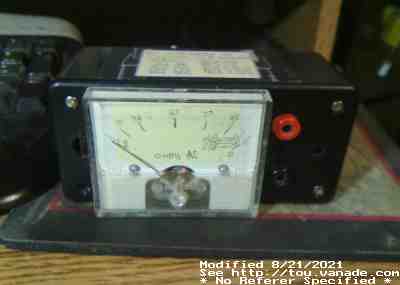
Meter with "crude hand drawn scale." Unfortunately the calibration resistors
I used made the scale look linear somehow.
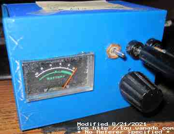
Second/"Butterdish" 3d printed case ESR meter with crappy 200µA meter. "Tuning" scale markings
are deceptively close if you take the number and divide by 2 (i.e. if you read
4, the ESR is actually 2 ohms).
The inductor in this one was self wound using the input filter of a dead
ATX PSU, I used 90 turns of #30 for the primary (new) and
9 turns of #26 (scavanged from original winding on the core) for the secondary.
About the ESR meter
This is my high frequency (about 60KHz) AC ohmmeter, which is based off of
Manfred's ESR meter.
Since I get really frustrated at point to point on perfboard I designed a PCB
for the circuit. Believe me I had enough wirewrap and perfboard for a while.
(And I just can't get myself to do deadbug proto.
Don't know why but it's just not my thing.) I suspect if you prefer using perf
board, you can use the PCB layout as a guide. I found a way to lay out the
board without jumpers.
Gerber files available are here, xpcb source is here.
The Op Amp
Note that I also used a TL082 instead of a TL062 or even TL072. It still
works. Since it's in a socket I'll see what happens with other op
amps such as LM358, LM1458, and maybe even an LM6142 RRIO which
is probably overkill. Why did I use a TL082? because I have a bunch of them...
And a lot of LM1458's... Maybe I should have used dual 741's because I have a
boatload of those along with LF355 and LF356... I wish I had a
few LM358 and LM324, these op amps should be pretty good.
Only a few LM6142's unfortunately. I think I may also have a TS512AN's...
I have a few RRIO TLV2374 too...
The LM1458 oscillated at a lower than expected frequency and apparently the
amplifier stage did not work. It figures, it's an ancient dual unit.
It probably does not like being run at 5V.
After noticing the LM358 not working well, the LM6142 will likely have the
same problem. It wasn't until I compared the datasheets of my op amp
stockpile until it was clear - the input impedence of the rail-capable
opamps is not nearly as high as the non rail-to-rail op amps.
The LM6142's inputs are just atrocious. I suppose you can look for other
JFET or CMOS op amps like LF353 or (I don't have any CMOS op amps to suggest),
just don't try to sub in bipolar op amps without circuit modification.
You do know what, after studying the circuit a bit more, it leaves a bit
to be desired. Due to the amplifier biasing I would imagine that there's
no reason why any op amp wouldn't work here, except for the fact that the
AC voltage in the original design seems to be biased strangely,
though it still works for the TL062/TL082/TL084. The other issue is
the fact it runs off of 5V: for many older op amps,
this is on the low end borderline of the usable operation region,
hence not getting enough voltage swing to drive the
meter.
The Detector amplifier
I had to tweak the gain of the detection, R8, with using the probably same T1
from a broken PC ATX power supply. With the approx 8:1 transformer I pulled
out, I needed to use a 10K resistor for R8 (originally 39K)
to get reasonable response. The higher gain made low resistances invisible
on the 200µA meter no matter what the pot setting was...
Also, if you're staring at the board and notice I have the wrong values on
the board, you're right. Good catch, I'm just using parts from my junkbox
(a vast majority of the parts are recycled!) and deemed some of the values
noncritical.
Circuit notes
Please, PLEASE put R11 (the potentiometer) somewhere easily accessible from
the outside.
The circuit is extremely temperature sensitive for me (hey wait, doesn't that
sound like bad capacitors?) and tweaking the resistor is needed fairly
frequently. However I've noticed a lot
of bad caps are really bad, and the meter error isn't such a big deal.
Just make sure you short the two leads occasionally and know exactly what your
"0 ohm" reading should be, and take it from there. Bad capacitors tend to
show up considerably different than the "0 ohm" reading - as ESR rises,
losses from charge/discharge increase generating more heat. This heat causes
more electrolyte to boil off, and causes a vicious cycle, destroying the
capacitor.
Though I used a 200µA meter in the second meter,
it does not work very well, full scale is hard to attain with the circuit as-is.
I was attempting a 1mA meter which won't work at all due to the limited output
voltage swing of the op amp. So please stick with 100µA or lower meter.
Perhaps increasing R8 along with increasing C6 may help.
Then again, I don't know about the ESR of the caps C2 (coupling capacitor
on primary side of transformer) and C3 (not marked on PCB, but it's the
capacitor coupling the probe, connected to R7 and R6). If these have
high ESR, then the scale reading won't go very high... So, time to test the
ESR of these caps... uhoh... Now how do I test the ESR of these caps... :-)
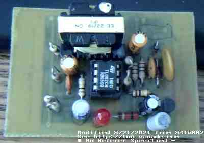
This is the PCB I used in the black meter, sans the variable resistor.
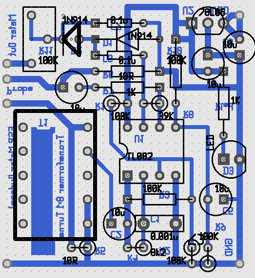
XPCB screenshot of the layout
Notes
As I drained down its first PP3/9V battery, the meter behaves very oddly and
claims infinite resistance for a dead short when the battery is weak.
Therefore check the battery when its behavior is unexpected. I measured the
current draw at around 7mA, which is the sum of the LED (I tried to target
around 1mA), quiescent power of the TL082 (4.5mA), and the dynamic power of
the oscillator plus power burned in R5.
Using a TL062 would definitely reduce power consumption...
Other uses
The ESR meter can be used to measure the ESR of AA and AAA
NiMH and NiCd batteries, which also should have very low ESR. If the
cells have over 1Ω ESR, those are bad cells. I'd even venture that
500 mΩ is bad too...
As the circuit will discharge batteries (due to the dual 10Ω
clamping resistors), don't leave it connected too long.
Do not measure the ESR of 9V batteries or anything higher than 2 volts.
Recycling
Well, I reused a lot of parts to build my ESR meter. Recycled parts used:
about half the resistors
all the capacitors
TL082
LED
Diodes
Transformer (did not rewind!)
LM78L05
New parts
other half of the resistors
Potentiometer R11
PCB (It is custom, after all.)
IC socket
Updates:
I made a smaller, 3D printed case for the old "butterdish" meter as I despised
the old case. I relocated
the LED on board as a meter side light so I can see if I left the meter on as
well as able to read the meter in subdued lighting. With the slide on lid I
no longer need a screwdriver to replace the battery.