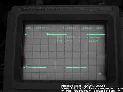
MiniDDS-AVR2313 output at square wave 1KHz with x10 probe on Tektronix 2440 DSO
MiniDDS-AVR2313 output at square wave 1KHz with x10 probe on Tektronix 2440 DSO
MiniDDS is a miniature Direct Digital Synthesizer for waveforms. Using an AVR 90S2313 or Tiny2313, digital waveform synthesis is generated by a microcontroller. Using an R-2R ladder to do digital to analog conversion, no special parts are needed. Note that when using 5% gold banded tolerance resistors, these exceed the resolution of the DDS (8-bit) so expect non-linearity. You may want to cherry pick out resistors (using a ohmmeter) that are very close to each other to get the best results - and remember it is a R-2R and matching R and 2R's matter, the difference between the R and the 2R's matters too (If you have a 1.000K for R, getting a 2.000K for the 2R will reduce error!) The errors are most clearly visible in the ramp waveforms. If you want to just buy and use resistors without hand binning, using 1% resistors for the R-2R ladder would be less work for getting decent linear results with less effort though even these exceed 8 bit resolution. If you must use resistors that don't quite match, such as 5% resistors, and don't want to cherry pick all identical resistors, you might want to at least sort the resistors from least to greatest and use the highest resistance resistors in the least significant bits for both the R and 2R resistors. Example: for 5% resistors you might sort the 1K's like 950Ω, 963Ω, 970Ω, 1.03KΩ, 1.05KΩ, etc., and likewise sort the 2K resistors like 1.90KΩ, 1.92KΩ, 1.95KΩ, 2.05KΩ, 2.10KΩ - and then put the largest resistances nearest the least significant bits. This will make it so you'll not notice the non-linearity error as much. The error will still be there of course, just you won't see a drop in voltage when you go from 00001111 to 00010000.
Theory of operation:
This DDS is done completely in AVR assembler. I used tavrasm, but gnu as(1)
should work. This software is kind of kludgy and depends on the behavior of
the AVR to run, specifically using its ZH/ZL register to speed up program
memory reads.
A 24 bit accumulator (made by YH (r28) YL (r29) and ZL (r31)) and a 24 bit increment (r24 XH(r25) and XL (r26)) is at the heart of the DDS. A 9 cycle endless loop routine performs the DDS operation. This routine increments the accumulator by the increment, and simply pulls the top 8 bits out of the accumulator (divide by 65536), using that as an index to one of the wave tables stored in program memory. As long as the incrementer remains less than 65536, the full waveform will be presented (though may have some THD due to the division by 65536). Higher than 65535, it will start skipping entries in the wave table, which may or may not be noticeable but adds even more THD up until it starts skipping so many that it goes below Nyquist sampling rate of the wave table, producing runt waveforms. This depends on the waveform stored in the wave table.
Wave tables are 256 entries long and stored in program memory as a constant. Depending on the complexity of the waveform, the max frequency that still faithfully generates that waveform will change. Sine waves are the most forgiving of course, and anything with hard edges (square, pulse, sawtooth) will likely have width errors (some of the pulses will be wider than others). The triangle wave is in between the sine and square wave characteristics.
An interrupt for the serial port handles updates to the configuration.
Due to the 65536 divide of the accumulator, anything increment that does not evenly divide into this will have a bit of jitter depending on the cycle. For low frequencies this will not matter much. Also due to the division necessary by the 9 cycle loop, frequency errors can be fairly significant though still less than 1% for the most part. Changing parameters will disrupt the waveform as it's an interrupt from the tight loop. Not only this, the waveform changes are abrupt - no attempt is made of a smooth transition from one wave to another. So remember this when you see a high frequency glitch!
My additions/changes to the code:
My take on this: This is very cute. It's simple. It's crude. It produces nasty waveforms. It's missing amplitude control. But it works, and generates nice waveforms for your oscilloscope.
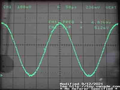
Sine wave at 4KHz
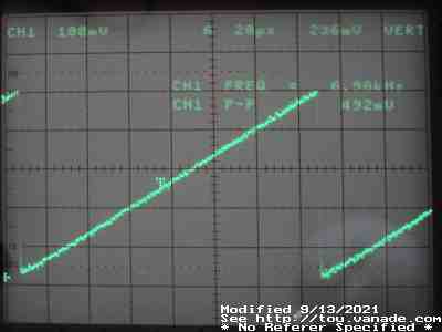
Sawtooth at 7KHz
Note that this is from an old 8-bit DSO and is a bit noisier than what you may see with an analog scope.
Code:
minidds code with my hacks
minidds hex file generated from above
Perl front end for Linux. Requires perl Device-Serial
The minidds.pl script is invoked:
minidds.pl [-h] [-f freq] [-t type] [-l serial] [-w]
Running without options will use /dev/ttyS0 and read back the current frequency.
-h - print out this terse help
-f freq - set output frequency
-t type - set waveform type. Currently 2=Sine 3=sawtooth up 7=triangle 5=square 6=pulse(does not always work at high frequency) 4=sawtooth down. This depends on the DDS firmware code you use
-l serialport - change serial port minidds is connected to
-w - write settings to eeprom - note you cannot save the flat line waveforms
Examples:
minidds.pl | Read back current frequency |
minidds.pl -f 440 | This changes just the frequency to 440Hz |
minidds.pl -t 5 | Switches to square wave |
minidds.pl -w | This just saves mode into eeprom for the next power up |
minidds.pl -f 3000 -t 2 -w | This sets a 3KHz sine wave and writes this mode into eeprom for next power up |
Schematic is the same for all versions of MiniDDS-AVR, so pick any off the web
until I can post my own. Note that you should add brownout detection (see
Atmel avr180 doc1051)
as the AT90S2313 suffers from EEPROM corruption if power supplies don't come up
and go down cleanly. If the firmware detects eeprom corruption, it will
switch back to default settings.
Links
Adding a PLL to increase speed for shortwave radio frequency synthesis (German)
Jesper's original MiniDDS page