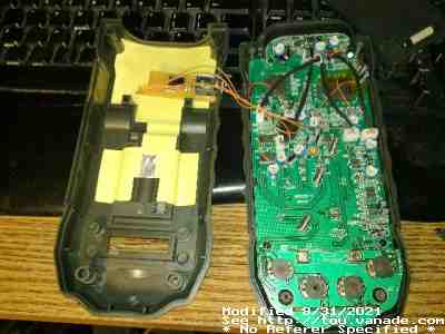
Both halves of the meter. Note that I used a small bit of perfboard with the isolator, resistors, and the 1/8" phono jack on it. The phono jack was from ratshack.
First written sometime in July 2013, updated a bit in October 2017
I bought a Centech P98674 a while ago from Harbor Freight Tools as I wanted to get an autoranging, 3¾ digit meter. I think the MS8229 is a fair meter, though after opening it multiple times, it's starting to show some creakiness. (I now use a B&K 4½ digit meter that's true RMS as a bench meter.) I liked the fact that it had fewer contacts on the multifunction switch as it is an autoranging meter, uses cheap AAA batteries1, and can even measure AC amperes. Much better than the freebies that Harbor Freight sometimes offers (and their lower 1MΩ input impedence), though it seems most or all of their meters were OEMed by Mastech like the Centech 92020 (Mastech M300) and Centech P33499 (Mastech M830B).
About the only thing that I was disappointed about the P98674 was that it had
no transistor hFE/gain check. As I work with transistors a lot, this was
actually a feature I use to measure estimate DC gain
without needing a test jig.
After finding out that this meter could be modded to add serial port support on EEVBlog, I just had to do it...but I used a slightly different technique than others on the web:
Apparently there were references to HW2SW (and another page on HW2SW ) but I only used them as a guide. Of course the serial port is still the same as all MS8229's, so the same 9600 baud, 8/N/1 is used. It sends bitmaps of what's on the display, and since the other pages describe them just fine, no sense repeating here. However, instead of the 1-channel optoisolator approach, I used a dual optoisolator IC (8-pin - NEC PS2521-2, but virtually any would do.) Note in the pictures that I have no switch to turn on serial! I'm using a 1/8" phono jack (stereo) on the meter to reduce the case drilling. Using a 1/8" phono plug from a broken pair of stereo headphones, I routed RTS, RxD, and GND to the meter (this is based off the connection diagram on the datasheet for the controller chip). At the loose end of the headphone cable I attached a DB9F. A 15KΩ resistor pulls the RxD pin to the DTR pin (which should be set LOW) of the DB9. Inside the meter on the board, I have a 220Ω resistor as current limiting in case of a short, then to the collector of one channel. The emitter of that channel goes back through the phono jack to RxD. To make this all work, RTS needs to be set high and DTR set low (optional, but increases SNR). You can also swap RTS and DTR if you want to match HW2SW behavior, this can be done at the DB9 - no need to hack the circuit board guts.
However here's the trick! Since RTS and GND is sent (for shielding, though it
may not be necessary) I hooked these up through a 2K ohm resistor to the second
optoisolator channel. Since RTS needs to be high to communicate to the meter,
this will turn on the other optoisolator. But what is the other transistor
channel used for?
Why, this answers the previous question: why do I need the switch?
I have that transistor pulling down on pin 84 to initiate RS232!
So both optoisolator channels are used to isolate RS232 from the meter.
Both halves of the meter. Note that I used a small bit of perfboard with the isolator, resistors, and the 1/8" phono jack on it. The phono jack was from ratshack.
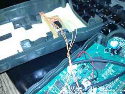
A little closer
Now you can see the 1/8" stereo jack. It's completely isolated from the meter guts.
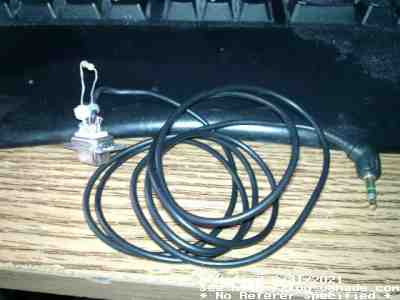
This is my ugly cable. It's not a straight through cable but it could,
but the SNR would be reduced somewhat. One loopback wire and a resistor is
used (see schematic).
Schematic that I used is here.
Battery life:
Yes having the meter turned on will eat batteries. But I've found the meter
to be very modest on power, with or without the mod. Power is being used to
drive the LED in the optoisolator but it's pulsed. The pulldown burns a little
power as well, but minimally less than what a switch would have done.
Also keep in mind, with RS232 turned on, the meter's power save will not
kick in. And if your RS232 port doesn't support all the handshake pins (like
if you were hooking this up to a minimal microcontroller), you may need to
incorporate the switch like other webpages do.
Software
I wrote the software for Linux in perl for the command line. Pretty much works the same as any other program. And this is another weird behavior that turns out to be good: When the script is killed, Linux would deassert RTS... This will turn off the optoisolator, which will then deassert the ENTX... and rs232 is automatically disabled, and the meter's power save will kick in!
Using CZn cells is a bit different. Here in the USA, an 8-pack AAA can be had for $1 and they hold 540mAh each. Two swaps plus two extra is available. Two PP3 CZn batteries can be found at $1, holding 400mAh. All other things being equal, the CZn solution is cheaper for the PP3 if you can get them for $0.50 a pop, as long as you can finish using the power in the battery before the electrolyte dries out.
Compared to my Fluke 77 however, it uses a PP3 and says it can run 1600h on a 400mAh battery, which means a current draw of 250µA. This is much better than all my other meters short of perhaps my analog meters which use the battery only when testing resistance. Battery costs should negligible on this meter other than it drying out. Alas the Fluke does not have a backlit display like the MS8229...